

Safety-Critical Castings: Hidden Quality Control Methods That Ensure Zero Defects
- Faisal Kapasi
- Feb 11
- 10 min read


Defects in safety-critical castings can lead to catastrophic failures, with potentially life-threatening consequences in aerospace, automotive, and medical applications. When a casting used in an aircraft engine or automobile braking system fails, lives are immediately at risk. However, behind every reliable casting lies a complex network of quality control processes that remain largely invisible to end-users.
Zero-defect manufacturing in the casting industry depends on rigorous quality control methods that go far beyond simple visual inspections. Traceability in casting operations ensures that each component’s history can be fully documented from raw material to final installation. Furthermore, sophisticated NDT casting inspection techniques can detect microscopic flaws that would otherwise remain hidden until failure. These comprehensive approaches, particularly when combined with advanced dimensional verification, have revolutionized quality control in castings for high-stakes applications.
This article explores the hidden quality assurance methods that manufacturers employ to achieve the perfect safety-critical casting—from raw material verification and dimensional accuracy to advanced non-destructive testing and mechanical validation techniques. We’ll also examine the certification standards that ensure consistency across the manufacturing process.
Raw Material and Mold Quality Checks Often Overlooked
Quality begins with what goes into the mold. The casting industry’s focus often gravitates toward final inspection methods, yet exceptional safety-critical castings depend equally on rigorous raw material and mold verification systems that occur before metal ever touches a mold cavity.
Spectrographic Analysis for Alloy Composition
The slightest deviation in elemental composition can dramatically alter mechanical properties in safety-critical castings. Optical Emission Spectroscopy (OES) serves as the cornerstone technology for foundries producing precision components. This analysis method utilizes an electrical source to heat and vaporize a metal sample’s surface at thousands of degrees Celsius, creating element-specific emission lines known as plasma. The spectrometer’s optical system then separates this light into wavelengths unique to each element, with intensity proportional to the quantity present.
Modern foundries implement OES before each metal pour because chemical composition critically influences physical and mechanical properties. A single pour can contain up to 25 different chemical constituents that must maintain precise balance. For instance, insufficient magnesium in an aluminum casting would prevent proper curing during heat treatment, rendering the component unsuitable for its intended purpose.
The process begins with a metal sample from the furnace that is machined to ensure a smooth surface before spectroscopic testing. The analysis results appear in a color-coded system, allowing engineers to make precise adjustments to the melt’s chemical composition. Essentially, this verification occurs at the earliest possible stage, preventing defects from materializing rather than detecting them afterward.
Sand Mold Moisture Control via Dielectric Sensors
Moisture content represents a critical yet often underestimated quality parameter in sand casting operations. Conventional moisture analysis methods suffer from extended processing times and poor accuracy—fundamental limitations for high-volume production. In response, advanced foundries now implement dielectric sensor systems that enable real-time moisture monitoring.
These systems typically operate within the 29-35 MHz frequency range, creating a “voltage difference platform” that remains stable regardless of minor frequency fluctuations. This stability makes this range ideal for accurate moisture measurement. The optimal sensor configuration includes one central probe (80mm length) surrounded by three edge probes (60mm length) positioned 25mm from center, with 5mm diameter probes.
Integration with Internet of Things (IoT) technology has further enhanced these systems. Networks of sensors connect to control units that convert analog moisture and temperature readings to digital signals for transmission to data centers. This automation allows foundries to maintain precise control over sand quality parameters without production delays. Studies show moisture content decreases with temperature increases, with levels typically maintained between 3-7% for optimal casting results.
Thermal Imaging of Mold Preheat Uniformity
Uneven temperature distribution across mold surfaces creates internal stresses, dimensional inaccuracies, and porosity defects that compromise casting integrity. Thermal imaging technology offers foundries a non-contact method for verifying uniform mold preheating before metal introduction.
Safety-critical applications require comprehensive temperature mapping across the entire mold surface and interior. Modern infrared cameras can detect temperature variations as small as 0.1°C, identifying potential cold spots that could cause premature solidification or hot spots that might generate excessive porosity.
For zero-defect manufacturing in casting operations, these three quality control methodologies represent the critical first line of defense. While often overshadowed by downstream inspection techniques, these preemptive verification systems establish the foundation for defect prevention rather than mere detection.
Dimensional Accuracy Verification Using Advanced Metrology
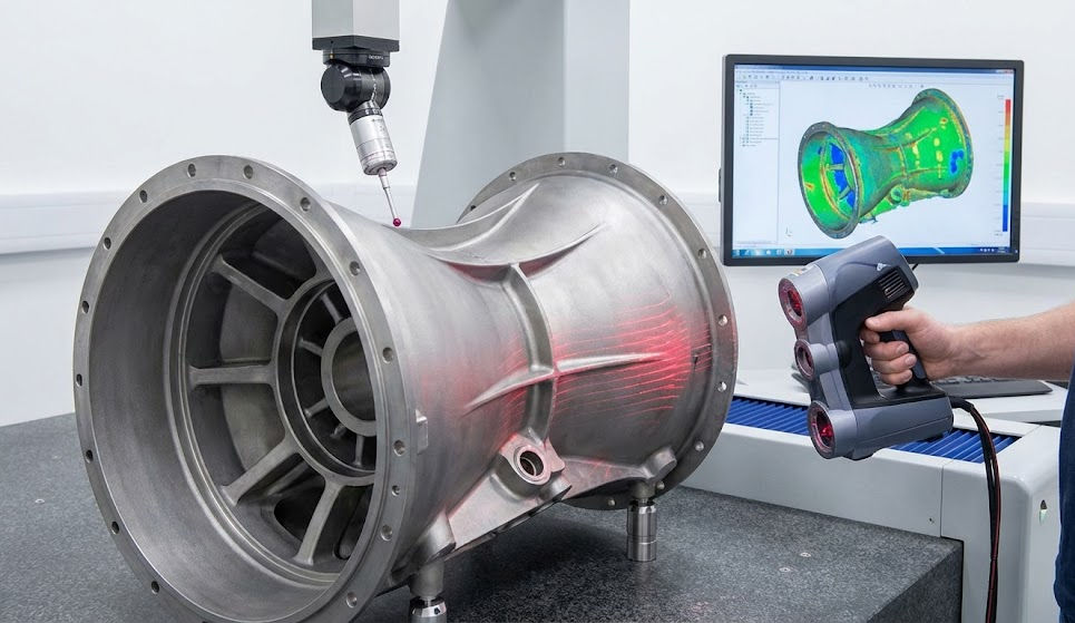
Dimensional accuracy stands as the foundational pillar in casting quality control. After material composition verification, determining if a casting meets exact geometric specifications becomes the crucial next step that dictates whether components will assemble correctly and function safely in critical applications.
Coordinate Measuring Machines (CMM) for Complex Geometries
Coordinate measuring machines represent one of the most crucial technologies in modern casting verification, capable of measuring complex geometries with exceptional accuracy—often achieving measurement uncertainties within micrometers. Since their introduction in the 1960s, CMMs have evolved from primarily manual instruments to sophisticated computer numerical control (CNC) systems that enable automated measurement routines with substantially improved repeatability.
Modern CMMs operate by utilizing a movable probe that contacts or optically measures specific points on a casting’s surface, capturing data points that software then processes to calculate dimensions, tolerances, and geometric relationships. For safety-critical castings, manufacturers often employ CMMs with flexible indexing wrists that allow engineers to tilt probes at various angles—a critical capability when accessing unusual shapes and difficult-to-reach features.
In casting production, CMM verification often occurs concurrently with manufacturing, allowing for quality checks at the final stage of production. This integration enables manufacturers to identify dimensional issues before parts advance further in the production process. Nevertheless, CMMs examine only specific points on a component—leaving uncertainty about what exists between those individual measurement points.
Laser Scanning for Real-Time Shrinkage Compensation
Complementing traditional CMMs, laser scanning technology offers a comprehensive solution for casting inspection by capturing entire surfaces rather than individual points. Unlike contact-based methods, 3D laser scanning rapidly maps complete component surfaces, generating detailed point clouds that reveal shrinkage issues undetectable through traditional techniques.
Notably, high-precision laser scanning can define localized shrinkage in cast components with remarkable accuracy—replicating organic-shaped sink areas to 2-3 ten-thousandths of an inch on small parts. This capability proves invaluable for troubleshooting tooling issues by developing surfaces of sink areas and using the resulting CAD geometry to modify tooling inserts.
Advanced scanning systems use color mapping to visualize whether sufficient material exists in castings to produce accurate final components. This visual representation simplifies complex data interpretation, allowing operators to quickly identify areas requiring adjustment. In safety-critical applications, manufacturers often perform cross-section silhouette comparisons with tight tolerance bands to detect under-size conditions where actual part boundaries fall inside reference boundaries.
Tool Wear Monitoring with Digital Profilometers
Tool deterioration directly impacts casting dimensional accuracy, making systematic wear monitoring essential for maintaining quality standards. Digital profilometry provides non-contact measurement of tool surface characteristics, detecting microscopic changes in mold geometries before they manifest as visible casting defects.
For safety-critical applications, manufacturers increasingly implement automated vision systems combined with artificial intelligence to analyze tool wear patterns in near-real-time. These systems capture high-resolution surface data, comparing measurements against baseline profiles to identify deviations that could compromise casting accuracy.
Modern digital profilometers can detect surface variations as minute as 0.1 micrometers—a level of precision necessary for aerospace and medical casting applications where microscopic deviations can lead to catastrophic failures. Specifically, advanced systems can measure critical parameters such as surface roughness, waviness, and form deviations across complex mold geometries.
The integration of these three metrology approaches creates a comprehensive dimensional verification system that addresses distinct aspects of casting accuracy. While CMMs provide precise measurement of specific points and features, laser scanning captures holistic surface data crucial for shrinkage compensation. Simultaneously, digital profilometry ensures tooling precision remains consistent throughout production runs. Together, these technologies form an indispensable verification chain in safety-critical casting manufacturing.
Non-Destructive Testing Methods Beyond the Basics

Beneath the surface of quality control lies a sophisticated world of internal inspection techniques that make zero-defect manufacturing possible in safety-critical castings. Advanced non-destructive testing (NDT) methods can reveal hidden flaws that would otherwise escape detection until catastrophic failure.
Phased Array Ultrasonic Testing (PAUT) for Internal Flaws
PAUT elevates conventional ultrasonic testing by using multiple independent transmitting and receiving sensors that enable higher-resolution internal imaging and deeper penetration. Unlike traditional ultrasonic testing that uses fixed angles, phased array technology allows the beam to sweep over various angles, creating a two-dimensional image similar to radiography. This capability makes PAUT particularly valuable for safety-critical castings with complex geometries.
The technology functions by controlling the propagation direction of ultrasonic beams through phase control, allowing for large-scale, rapid scanning. Moreover, PAUT can detect minute flaws at great depths within castings, making it effective for thick-walled components where other NDT methods prove impractical. For anisotropic materials like welds in safety-critical castings, PAUT provides superior flaw detection sensitivity based on inspection conditions.
Computed Radiography vs Traditional X-ray in Castings
Computed radiography (CR) modernizes conventional X-ray inspection by replacing traditional film with photo-stimulable phosphor imaging plates. After exposure to penetrating radiation, these plates are scanned to create digital images through photostimulable luminescence, providing permanent digital archives immune to degradation issues that plague conventional film.
CR offers significant advantages for quality control in castings, including substantial reduction in exposure times compared to conventional radiography while maintaining the same energy levels. Additionally, CR provides higher resolution images that can be digitally shared among stakeholders, facilitating faster decision-making. The technology excels at examining castings with varying thicknesses due to its wide dynamic range.
Eddy Current Testing for Surface Crack Detection in Non-Ferrous Alloys
Eddy current testing presents a contact-free electromagnetic method primarily used for non-ferromagnetic materials. This technique works by creating a magnetic field that induces opposing currents in conductive materials—defects disrupt these currents, creating detectable impedance changes in the testing coil.
For non-ferrous casting alloys, eddy current testing offers exceptional sensitivity to surface-breaking cracks, detecting defects as small as 0.5mm. Furthermore, the method proves effective at identifying near-surface flaws that might escape visual inspection. Unlike many NDT methods, eddy current testing can penetrate non-conductive surface coatings without compromising detection capabilities.
The integration of these advanced NDT methods creates a comprehensive verification system that ensures safety-critical castings meet stringent quality requirements. By detecting microscopic flaws before components enter service, these technologies form an essential link in the quality assurance chain for high-stakes applications.
Destructive Testing for Mechanical Integrity Validation

Beyond inspection lies validation—the critical process of verifying a casting’s mechanical properties through controlled destruction. Despite its destructive nature, this testing provides conclusive data about material performance under stress, thereby ensuring safety-critical castings meet stringent standards.
Tensile Testing for Yield and Ultimate Strength
Tensile testing stands as the foundation of mechanical validation, determining how castings respond to pulling forces. This procedure measures two critical properties: yield strength—the stress at which permanent deformation begins, and ultimate tensile strength—the maximum load a casting can withstand before fracture. For safety-critical applications, tensile specimens are often produced with reference dies designed specifically for consistent evaluation.
The test involves applying increasing axial force to a standardized specimen until failure occurs. Engineers typically conduct these tests on machines using crosshead speeds of 1.5-2 mm/min while measuring strain with a 25-mm extensometer. The resulting data provides crucial insights into both strength and ductility—essential parameters for components subject to operational stresses.
Charpy Impact Testing for Fracture Resistance
Unlike tensile testing, which applies gradual force, Charpy impact testing evaluates a casting’s response to sudden loading—a critical consideration for safety-critical components. This standardized procedure measures energy absorption during fracture, indicating toughness and resistance to brittle failure.
According to industry standards, the test employs a swinging pendulum that strikes a notched specimen. For grade B+ materials, AAR M201 standard requires that three samples must absorb an average energy above 15 ft-lb when tested at 20°F. The resulting energy values help identify the transition temperature between brittle and ductile behavior, typically occurring between 20°F and 60°F.
Brinell vs Rockwell Hardness Testing in Cast Surfaces
Hardness testing—perhaps the most common mechanical property evaluation—measures a casting’s resistance to indentation. Although related, Brinell and Rockwell methods differ significantly in application and measurement technique.
The Brinell test applies a 10mm hardened steel ball with forces ranging from 500-3000 kgf. After removing the load, technicians measure the indentation’s diameter using a microscope and calculate the Brinell Hardness Number. Conversely, Rockwell testing measures indentation depth rather than width, using either a diamond cone or smaller steel ball.
Each method offers distinct advantages for cast surface evaluation: Brinell provides averaged results over larger areas—ideal for heterogeneous castings with coarse grain structures. In contrast, Rockwell testing delivers faster results with direct digital readouts, making it appropriate for high-volume production quality control.
Traceability and Certification in Safety-Critical Castings
The final cornerstone of quality control in safety-critical castings rests on comprehensive traceability systems that document every step from raw material to final inspection. Even after rigorous testing, manufacturers must prove component history and compliance with industry standards.
Batch-Level Traceability Using QR and RFID Tags
Modern casting manufacturers implement unique identification through RFID tags and QR codes to track components throughout production. This technology enables complete chain traceability from raw material through distribution. Foundries assign unique identifiers to crates and components, linking physical products with digital records. RFID antennas subsequently detect all movement, with transfers automatically logged in centralized systems . For safety-critical applications, this traceability prevents potentially catastrophic mix-ups between batches with different metallurgical properties.
ISO 9001 and ASTM A903 Compliance for Cast Components
Safety-critical castings typically require certification under multiple standards, including ISO 9001 and aerospace-specific AS9100. ASTM A903 specifically governs acceptance criteria for surface inspections using magnetic particle and liquid penetrant methods. Under this standard, manufacturers must certify that inspections followed appropriate practices (Practice E 165 for liquid penetrant inspection or Guide E 709 for magnetic particle inspection). Certified test reports must include customer name, purchase order number, material description, NDE procedure details, acceptance criteria, inspector name, and qualification level.
Digital Recordkeeping for Audit-Ready Quality Logs
Digital quality records replace traditional paper documentation, creating searchable archives that facilitate immediate retrieval during audits or inspections. These systems track version history, set access permissions, and ensure only authorized personnel access sensitive information. According to industry regulations, foundries must maintain inspection and test records for a minimum of 10 years. Consequently, digital archives provide foundries with audit readiness while demonstrating compliance to regulators and customers alike.
Conclusion
Behind every safety-critical casting lies an intricate quality assurance framework that remains largely invisible to end-users. This comprehensive approach begins with meticulous raw material verification through spectrographic analysis and extends to sophisticated mold quality controls. Consequently, manufacturers establish a solid foundation for defect prevention rather than mere detection.
Dimensional accuracy verification represents another critical pillar in this quality control architecture. Coordinate measuring machines, laser scanning technology, and digital profilometers work together to ensure castings meet exact specifications down to the micrometer level. These methods allow manufacturers to detect and address potential issues before components advance further in production.
Advanced non-destructive testing methods significantly enhance the ability to identify hidden flaws that might otherwise remain undetected. Phased array ultrasonic testing, computed radiography, and eddy current testing each serve unique purposes in revealing internal defects without compromising component integrity. Though invisible to the naked eye, these microscopic flaws could lead to catastrophic failures if left undiscovered.
Destructive testing, albeit sacrificing sample components, provides undeniable confirmation of mechanical properties. Tensile testing reveals how materials respond to pulling forces, while Charpy impact testing evaluates sudden load responses. Additionally, hardness testing measures resistance to indentation, completing the mechanical validation process essential for safety-critical applications.
Lastly, robust traceability and certification systems ensure every component’s history remains documented from raw material to final installation. This meticulous record-keeping, coupled with adherence to international standards, creates accountability throughout the manufacturing process.
The zero-defect approach to safety-critical castings therefore depends on this multilayered quality control framework. When lives depend on casting integrity—whether in aircraft engines, automotive braking systems, or medical devices—these hidden quality assurance methods become essential, not optional. The extraordinary reliability we expect from these components stems directly from these rigorous, often unseen processes that transform basic metallurgy into life-saving engineering.


Comments